Infinite plate with a hole: continuous pressure
1 Objective
Verify the nearly incompressible, small-strain response of an infinite elastic plate containing a circular traction-free hole. The test compares displacement and axial stress throughout the modeled volume with the Kirsch solution, and checks their convergence under mesh refinement. It specifically exercises continuous pressure in the stabilized mixed formulation.
2 Geometry
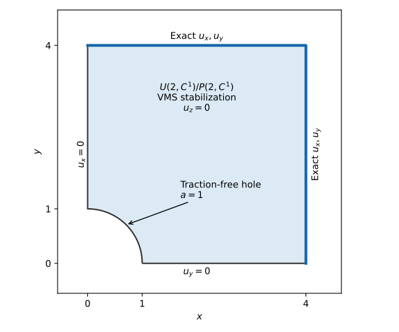
The hole radius is \(a=1\). Symmetry reduces the domain to \(0\leq x\leq4\), \(0\leq y\leq4\), \(x^2+y^2\geq a^2\). A three-dimensional extrusion of fixed thickness \(t=0.25\) represents plane strain. The thickness remains fixed across the refinement study. The exact displacement is imposed on the artificial outer boundary, so the finite computational domain represents a restriction of the infinite-domain solution without a far-field truncation approximation.
3 Material
The material is isotropic and linearly elastic, with \(E=100000\) and \(\nu=0.49999\) in a consistent unit system. The shear modulus is \(\mu=E/[2(1+\nu)]\), and the bulk modulus is \(K=E/[3(1-2\nu)]\). Thus \(K/\mu\approx50000\), making volumetric locking a demanding concern. Small-strain kinematics are used throughout; this case does not test finite strain or plasticity.
4 Loading & boundary conditions
The remote tensile stress is \(T=10\) in the \(x\) direction. There are no body forces. The circular boundary is traction free. On \(x=0\), \(u_x=0\); on \(y=0\), \(u_y=0\). On \(x=4\) and \(y=4\), both in-plane displacement components equal the analytical solution below. Abaqus’s DISP user subroutine supplies these values. The condition \(u_z=0\) throughout the extrusion enforces plane strain, including its nonzero out-of-plane stress. This is not a plane-stress coupon.
The translated IGA model imposes displacement conditions by penalty with coefficient \(10^{10}\). The resulting error therefore includes boundary-enforcement error as well as approximation and geometric integration errors.
5 Mesh & discretization
The displacement and independent pressure use the same quadratic \(C^1\) spline space, \(U(2,C^1)/P(2,C^1)\). Pressure is retained as a global unknown. Variational multiscale (VMS) stabilization supports the equal-order pair. Static condensation, pressure macro-elements, and discontinuous-pressure aggregation are disabled. The test checks the translated UEL export for continuous pressure before solving, preventing an accidental displacement-only or discontinuous-pressure run from supplying this study’s evidence.
Three immersed meshes use in-plane sizes \(h=1/2\), \(1/4\), and \(1/8\). The through-thickness size is \(1/8\) at every level; the exact solution is independent of \(z\). Small-cell extension uses a volume-ratio threshold of \(0.1\). The CAD tessellation size is \(h/2\), refined together with the background mesh. Each mesh has its own CTest and workspace. A separate fixture-dependent study CTest checks convergence using all three completed simulations.
6 Reference & accepted solutions
Kirsch’s classical solution provides the stress concentration around a circular hole in an infinite isotropic elastic medium; see the plane-strain benchmark in [1]. The following expressions use tensile-positive stress and a remote load directed along \(x\).
Let \(r=\sqrt{x^2+y^2}\), \(\theta=\operatorname{atan2}(y,x)\), \(q=a/r\), and \(\kappa=3-4\nu\). The plane-strain displacements are
\[ u_x=\frac{Ta}{8\mu}\left[ \frac{r}{a}(\kappa+1)\cos\theta +2q\{(\kappa+1)\cos\theta+\cos3\theta\} -2q^3\cos3\theta\right], \]
\[ u_y=\frac{Ta}{8\mu}\left[ \frac{r}{a}(\kappa-3)\sin\theta +2q\{(1-\kappa)\sin\theta+\sin3\theta\} -2q^3\sin3\theta\right],\qquad u_z=0. \]
The axial stress used in the volume comparison is
\[ \sigma_{xx}=T\left[1-q^2\left(\frac32\cos2\theta+\cos4\theta\right) +\frac32q^4\cos4\theta\right]. \]
On the hole boundary, the radial and shear tractions vanish, while \(\sigma_{\theta\theta}=T(1-2\cos2\theta)\). In particular, \(\sigma_{xx}(0,a)=3T=30\). This peak is an analytical interpretation of the solution, not a separately enforced pointwise numerical acceptance criterion. The plane-strain relation is \(\sigma_{zz}=\nu(\sigma_{xx}+\sigma_{yy})\).
For each quantity \(f\), the test computes
\[ e_f=\frac{\left[\int_\Omega\lVert f_h-f_*\rVert^2\,dV\right]^{1/2}} {\left[\int_\Omega\lVert f_*\rVert^2\,dV\right]^{1/2}}. \]
Physical reference positions X, reference volume weights dV, directly evaluated U, and actual frame-matched mixed S are exported through the default-off --quadrature-output option in <job>_iga_quadrature.sql (format version 1). The postprocessor integrates vector displacement and axial stress errors from these solver samples and records them in global_l2_metrics.json. L2 postprocessing needs only the quadrature file; visualization remains in <job>_iga_results.sql (schema 5). Both cut and ordinary cells contribute on the represented trimmed geometry. Numerical integration uses the solver’s volume quadrature and does not independently bound quadrature error.
The test-owned problem definition records all tolerances. The acceptance limits for \((e_u,e_{\sigma_{xx}})\) are \((0.01,0.2)\), \((0.005,0.1)\), and \((0.002,0.05)\) from coarse to fine. Both errors must be finite and nonnegative. The integrated domain volume must also agree with \(t(b^2-\pi a^2/4)\), with \(b=4\), within \(0.1\%\). For each quantity, a least-squares fit of \(\log e\) against \(\log h\) must give a slope greater than \(0.5\). This is a practical convergence check, not a claim that the full asymptotic spline rate has been reached.
7 Results
7.1 Axial stress field
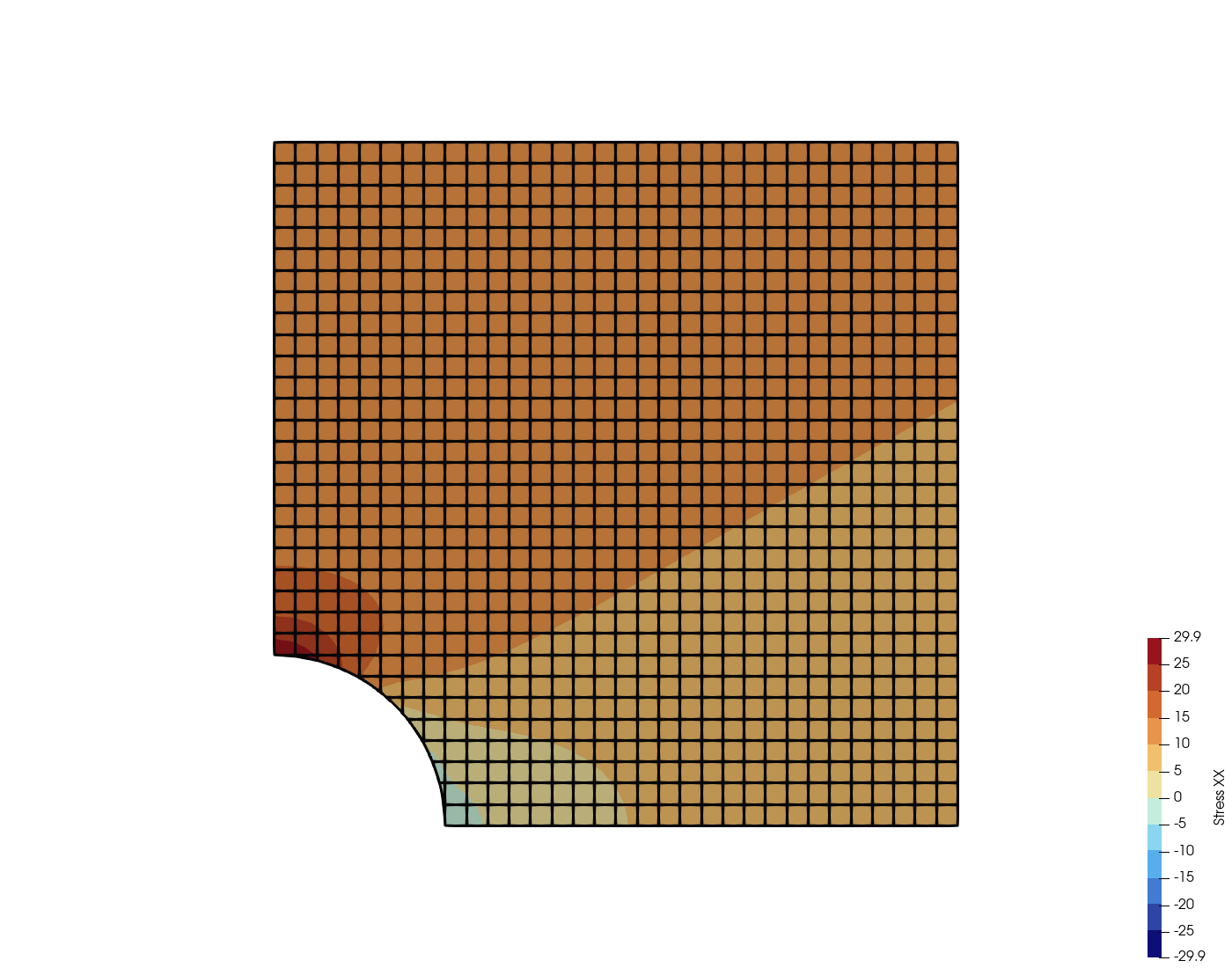
The following image is generated at documentation-render time from the finest mesh’s final simulation results, using the same ParaView reader and rendering helper as the other verification problems. Color shows axial stress \(\sigma_{xx}\) on the undeformed plate; the overlaid lines show the trimmed Bézier elements. The concentration near \((x,y)=(0,a)\) is visible directly in the computed field.
7.2 Quantities of interest
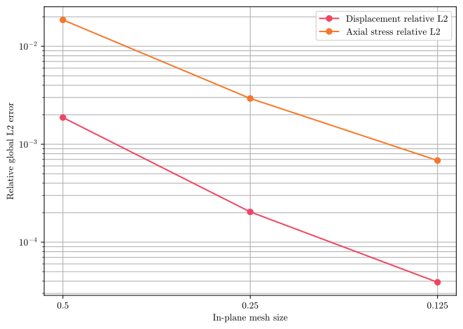
The tables and plot below are generated from the simulation and study artifacts. The evidence banner identifies missing, stale, or current results. Rendering never runs the solver or changes acceptance criteria.
| h | Displacement relative L2 | Axial stress relative L2 | |
|---|---|---|---|
| 0 | 0.500 | 0.001873 | 0.018607 |
| 1 | 0.250 | 0.000204 | 0.002934 |
| 2 | 0.125 | 0.000039 | 0.000682 |
| Quantity | Fitted convergence rate | |
|---|---|---|
| 0 | displacement_l2_rel | 2.793654 |
| 1 | s11_l2_rel | 2.384603 |
8 Discussion
This study verifies the stabilized continuous-pressure formulation against an exact solution at one nearly incompressible Poisson ratio. Refinement reduces both geometric and approximation errors. It does not isolate either contribution, and a successful study alone does not establish inf-sup stability for arbitrary meshes, demonstrate performance at exactly \(\nu=0.5\), or verify pressure itself in a norm. The axial stress includes the mixed volumetric response, but other stress components and pressure oscillations require separate checks.
The exact outer displacement avoids confusing finite-plate boundary effects with numerical error. The fixed extruded geometry also makes the three runs comparable. Each run exports the model journal, decks, provenance, problem definition, global norms, and structured checks; the study records the exact contributing workspaces and their artifact digests.
References
[1]
Itasca, “Cylindrical hole in an infinite elastic medium.” Accessed: Sep. 28, 2026. [Online]. Available: https://docs.itascacg.com/itasca900/3dec/docproject/source/examples/CylindricalHoleInAnIEM.html
Appendix
8.1 Reproduce the study
From the repository root, with the configured Coreform IGA build, Abaqus/Standard and Abaqus/CAE licenses, and the GNU Fortran toolchain available:
cmake --build ../build_lin64 --config Release --target \
  coreform_iga_mesh abaqus_interop_exe \
  uel_usub uelmat_usub uexternaldb_usub uvarm_usub
./build docs cifa tests --problem infinite-plate-with-hole
CIFA_DISABLE_VIZ=0 ./build docs cifa render-page \
  verification-manual/problems/solid_mechanics/linear_elastic_stress/infinite-plate-with-hole/infinite-plate-with-hole.qmd
The selected test plan contains three simulations and one convergence check. No external CAD download is required: Abaqus/CAE constructs the geometry. Compiler, solver, and source-version information is recorded with the evidence.
8.2 Capabilities exercised
When evidence is available, the table uses passing simulation and study artifacts; the shared banner identifies their revision and any unverified staleness. Each row must satisfy the linked capability card’s evidence contract; declaring a capability in a test does not, by itself, create evidence.
No qualifying capability evidence was generated for these run artifacts.
8.3 Download artifacts
Download verification artifacts (ZIP)
8.3.1 Geometry CAD files
No separate CAD file is required for this problem; the geometry is fully defined in the Abaqus/CAE journal files.
8.3.2 Abaqus/CAE journal files
3 generated Abaqus/CAE journals are available.
8.4 Supported Abaqus keywords
The decks below are reproduced from the verification tests’ Abaqus input files with comments stripped and instance-specific names (sets, materials, files) redacted to <placeholders>.
Noteinfinite_plate_with_hole.inp outline
*Heading
*Preprint, echo=NO, model=NO, history=NO, contact=NO
*Include, input=<iga-mesh-inp>
*System
*Material, name=<material>
*Elastic
100000., 0.49999
*User Output Variables
1,
*Boundary
<node-set>, 3, 3
*Step, name=<step>, nlgeom=NO, unsymm=YES
*Static
1., 1., 1e-05, 1.
*Boundary, user
<node-set>, 1, 1, 1.
*Boundary, user
<node-set>, 2, 2, 1.
*Restart, write, frequency=0
*Output, field
*Node Output
U,
*Element Output, position=AVERAGED AT NODES, directions=YES
S,
*Node Output
U
*Output, history, frequency=0
*End Step
8.5 Provenance
The records below identify the execution environment and verification basis for every CTest artifact reported on this page.
NoteTest_abaqus_verification_infinite_plate_with_hole_immersed_h0p2
| Parameter | Value |
|---|---|
| Evidence type | Numerical verification |
| CTest result | Passed (Release) |
| Verification result | Passed — 4/4 enforced criteria passed |
| Test date | 04-Nov-2026 19:40:54 |
| Operating system | Ubuntu 24.04.5 LTS |
| Coreform IGA version | 2026.11+72575 |
| Source revision | e48e5098b2f8 |
| Abaqus version | Abaqus 6.26-4 |
NoteTest_abaqus_verification_infinite_plate_with_hole_immersed_h1p2
| Parameter | Value |
|---|---|
| Evidence type | Numerical verification |
| CTest result | Passed (Release) |
| Verification result | Passed — 4/4 enforced criteria passed |
| Test date | 04-Nov-2026 19:41:02 |
| Operating system | Ubuntu 24.04.5 LTS |
| Coreform IGA version | 2026.11+72575 |
| Source revision | e48e5098b2f8 |
| Abaqus version | Abaqus 6.26-4 |
NoteTest_abaqus_verification_infinite_plate_with_hole_immersed_h2p2
| Parameter | Value |
|---|---|
| Evidence type | Numerical verification |
| CTest result | Passed (Release) |
| Verification result | Passed — 4/4 enforced criteria passed |
| Test date | 04-Nov-2026 19:41:45 |
| Operating system | Ubuntu 24.04.5 LTS |
| Coreform IGA version | 2026.11+72575 |
| Source revision | e48e5098b2f8 |
| Abaqus version | Abaqus 6.26-4 |
NoteTest_abaqus_verification_study_infinite_plate_with_hole_immersed_p2
| Parameter | Value |
|---|---|
| Evidence type | Numerical verification |
| CTest result | Passed (Release) |
| Verification result | Passed — 2/2 enforced criteria passed |
| Test date | 04-Nov-2026 19:47:16 UTC |
| Operating system | — |
| Coreform IGA version | Not applicable — postprocessing-only CTest |
| Source revision | e48e5098b2f8 |
| Abaqus version | Not applicable — postprocessing-only CTest |