Local refinement toward a feature
Local refinement is an experimental capability. Refinements are authored through the scripting interface; a graphical dialog in the Coreform IGA toolset is planned.
1 Description
In this problem we will locally refine an immersed Coreform IGA mesh toward a small geometric feature. We continue directly from the thin plate with a hole example — complete that example first, since we reuse its model, mesh, and job.
The plate’s stress concentration lives at the edge of the hole, and that is where mesh resolution pays off: refining the entire background mesh sharpens the answer but multiplies the element count everywhere, including the far field where the stress is essentially uniform.
Local refinement instead refines the background mesh only near the hole: you name the hole’s surface in Abaqus/CAE and attach a refinement to the mesh that points at that set. The mesher then refines every background cell the surface touches, level by level, down to the resolution you request.
2 How local refinement works
The pieces fit together as follows:
- In Abaqus/CAE you create a named assembly set containing the feature’s faces.
- You add a refinement to the part’s Coreform IGA mesh, naming that set as its region.
- When the Coreform IGA job writes its
<job>.cffile, both the set and the refinement are exported into the file’s geometry description. - The Coreform IGA meshing step reads them and builds a hierarchical spline basis.
The refinement is part of the mesh definition, so it is stored in the model database and travels with it: regenerating the .cf file or resubmitting the job preserves it, and it survives saving and reopening the .cae file.
Everything downstream (trimming, the Abaqus solve, visualization) then works exactly as it does for a uniform mesh.
3 Naming the feature in Abaqus/CAE
Open the model database from the thin plate with a hole example. The only adaptivity-specific modeling step happens in the Assembly module: create a set containing the hole’s inner cylindrical face.
- In the model tree, expand Assembly and double-click Sets.
- In the Create Set dialog, enter the name
holeand click Continue. - In the viewport, select the hole’s inner cylindrical face, and click Done.
The equivalent scripting-interface command selects the hole face by a bounding box that contains the hole but stops short of the plate’s outer faces:
inst = mdb.models["PWH-Kt"].rootAssembly.instances["Plate-1"]
hole_faces = inst.faces.getByBoundingBox(
    xMin=-1.1, xMax=1.1,   # the hole has radius 1 at the origin;
    yMin=-1.1, yMax=1.1,   # the plate's outer faces extend to x = +/-5, y = +/-2.5
    zMin=-1.0, zMax=1.0,
)
mdb.models["PWH-Kt"].rootAssembly.Set(faces=hole_faces, name="hole")
Create the set on the assembly, not on the part. An assembly set is exported with its bare name (hole); a part-level set is prefixed with the instance name, so sets=["hole"] would not match it.
4 Adding the refinement
The refinement attaches to the Coreform IGA mesh you created in the original example. Because the Plate-1 instance is dependent, that mesh lives on the Plate part. Run the following in the Abaqus/CAE command line interface:
from coreform.mesh import CadEntitiesRegion

mesh = mdb.models["PWH-Kt"].parts["Plate"].customData.CoreformIGA.mesh

mesh.Refinement(
    "hole_edge",
    level=2,
    region=CadEntitiesRegion(sets=["hole"], offset=0.1),
)
mesh.setValues(refinementBalance="two_to_one")"hole_edge"names the refinement. The name is yours to choose and must be unique within the mesh; it becomes the refinement’s label in the model file, prefixed with the instance name (Plate-1_hole_edge).level=2refines two levels deep. Each level halves the element size, so the in-plane element size at the hole edge goes from0.3to0.075.sets=["hole"]selects the region: refine cells that the named CAD surfaces touch. More than one set may be named.offset=0.1widens the catch: cells within that distance of the surface refine too, not only the cells it passes through. About a third of a background cell works well — it keeps the refined band snug against the feature while avoiding lone coarse cells grazing the surface. Pass0.0for the exact-touch band.refinementBalance="two_to_one"enforces 2:1 admissibility: after the region-driven refinement, additional cells are refined so that no two face-adjacent elements differ by more than one level, keeping the element-size transition gradual. Pass"none"to leave the mesh exactly as the regions describe it.
Editing and removing work the same way: mesh.setRefinementValues("hole_edge", level=3) changes one in place, mesh.refinementByName("hole_edge") reads it back, and mesh.deleteRefinement("hole_edge") removes it.
4.1 Tapering across levels
Each refinement carries a single region, applied at every level up to its own. To cast a wider net at the coarse level and tighten toward the surface at the deepest one, add one refinement per level:
mesh.Refinement("hole_L1", level=1, region=CadEntitiesRegion(sets=["hole"], offset=0.6))
mesh.Refinement("hole_L2", level=2, region=CadEntitiesRegion(sets=["hole"], offset=0.3))
4.2 Other regions
If your feature has no convenient named surface, two purely geometric regions are available:
from coreform.mesh import SphereRegion, BoxRegion

SphereRegion(center=(0.0, 0.0, 0.0), radius=1.5)              # a ball
SphereRegion(center=(0.0, 0.0, 0.0), radius=1.5, inner_radius=0.8)  # a spherical shell
BoxRegion(min_corner=(-1.1, -1.1, -1.0), max_corner=(1.1, 1.1, 1.0))
5 Meshing and solving
Submit Job-PWH-Kt from the Coreform IGA for Abaqus Job Manager, exactly as in the original example. The job writes the refinement into the .cf file, the meshing step picks it up automatically, and the remaining pipeline (interop, the Abaqus solve, and post-processing) proceeds as it does for a uniform mesh.
The meshing log reports how many cells were refined at each level, per part, along with any additional cells forced by 2:1 balancing.
6 What to expect
The refined mesh concentrates its added degrees of freedom in a band around the hole: the level-2 elements resolve the stress gradient at the hole edge while the plate’s far field stays at the coarse background resolution.
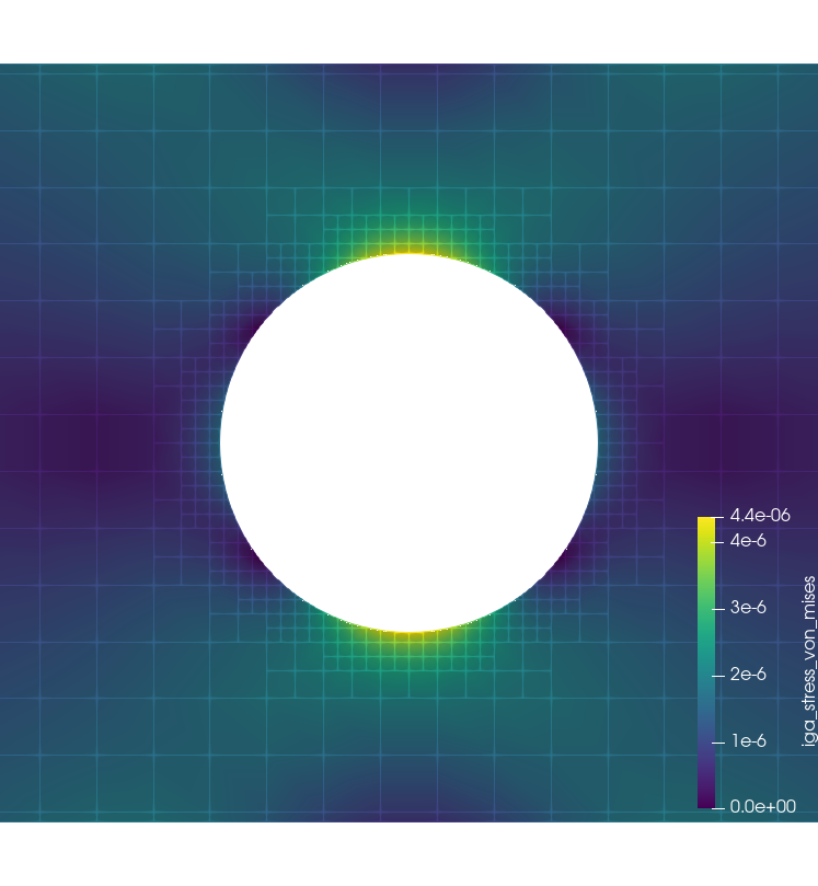
Compare the maximum principal stress along the line probe from the original example against the uniform-mesh run — the refined mesh sharpens the peak at the hole edge for a small fraction of the element count a uniformly-fine mesh would need.